 EN
EN
 AR
AR
 BG
BG
 HR
HR
 CS
CS
 NL
NL
 FI
FI
 FR
FR
 DE
DE
 EL
EL
 IT
IT
 KO
KO
 NO
NO
 PL
PL
 PT
PT
 RO
RO
 RU
RU
 ES
ES
 SV
SV
 ID
ID
 LT
LT
 SR
SR
 UK
UK
 VI
VI
 HU
HU
 TH
TH
 TR
TR
 FA
FA
 MS
MS
 HY
HY
 AZ
AZ
 KA
KA
 BN
BN
 LO
LO
 LA
LA
 NE
NE
 MY
MY
 KK
KK
 KY
KY

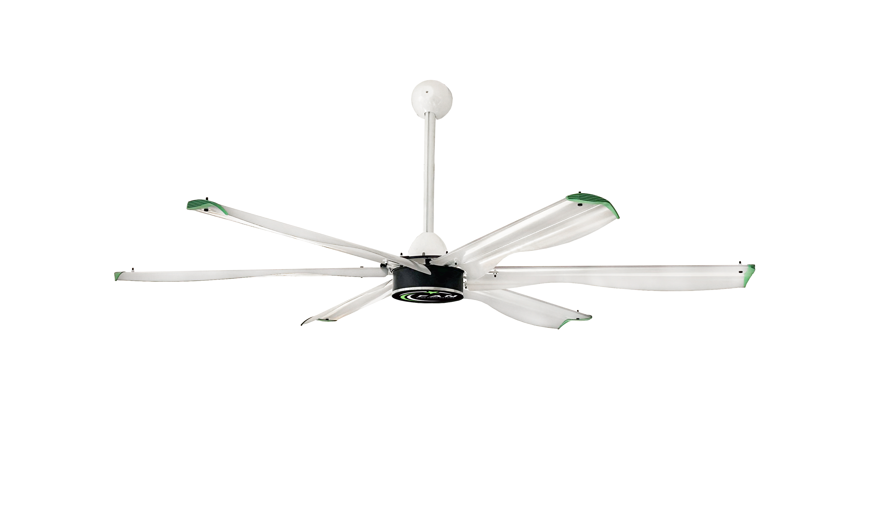
HVLS Fan Placement Strategy for Maximum Efficiency
Ceiling Height and Clearance Requirements for Optimal HVLS Fan Performance
For maximum efficiency, HVLS fans require precise ceiling height and clearance. Industry best practice recommends mounting fan blades 10 to 15 feet above the finished floor—with at least 3 to 5 feet of vertical clearance between blade tips and the ceiling. This spacing ensures unimpeded air intake and minimizes turbulence that degrades performance. In facilities with mezzanines or variable ceiling heights, placement must be zone-specific to prevent air stratification. Fan diameter should be proportionate to ceiling height: larger diameters (e.g., 24 ft) suit high-bay warehouses (>30 ft), while smaller models (10–16 ft) work best in lower-clearance spaces like distribution centers or manufacturing floors. Proper sizing and elevation reduce HVAC load and improve energy efficiency across the facility.
Avoiding Obstructions: Beams, Sprinklers, and Machinery in HVLS Fan Layouts
Obstructions—including structural beams, sprinkler heads, conveyors, and tall machinery—disrupt laminar airflow and create stagnant zones. To preserve performance, position fans in open bays or centered between racking aisles—not directly over dense storage, equipment, or traffic lanes. Maintain a minimum horizontal clearance of 4 feet from any beam, ductwork, or overhead utility line. For fire safety compliance, mount fans at least 3 feet below sprinkler deflectors to avoid impeding water dispersion; many manufacturers specify this as a hard requirement per NFPA 13. In dynamic environments, avoid downdraft paths that could dislodge debris or interfere with material handling. A pre-installation site survey mapping all overhead elements is essential to finalize layout and prevent costly repositioning.
Fan Spacing Guidelines to Ensure Uniform Airflow Coverage Across Warehouse Zones
Uniform coverage hinges on strategic spacing—not density. HVLS fans should be placed 60 to 100 feet apart, depending on blade diameter and target air velocity (typically 30–60 fpm at occupant level). Overlapping airflow patterns are critical: each fan’s effective radius should extend to the adjacent unit’s center point. For rectangular spaces, a grid pattern with spacing equal to 30–50 times the fan’s blade pitch diameter provides consistent results. High-occupancy zones—like packing stations or break areas—benefit from tighter spacing (e.g., 60 ft); low-activity storage zones can use wider intervals (up to 100 ft). Always validate spacing using manufacturer-recommended coverage charts or CFD modeling—especially where racking, columns, or irregular layouts exist. Well-spaced fans achieve full coverage with fewer units, lowering both capital cost and long-term energy use.
Structural Readiness: Mounting and Load-Bearing Requirements for HVLS Fans
Evaluating Ceiling Structure and Beam Integrity for HVLS Fan Mounting
HVLS fans weigh up to 150 lbs—and generate significant dynamic forces during operation—so mounting must rely on structural-grade supports only. Acceptable anchors include I-beams, steel rafters, or reinforced concrete slabs rated for industrial loads. Wood trusses, suspended ceilings, or lightweight roof decks are not suitable without engineering reinforcement. A licensed structural engineer must assess load paths, connection points, and existing member integrity before installation. Their report should confirm suitability for both static weight and operational vibration, and specify required reinforcements—such as gusset plates or supplemental bracing—if needed. Skipping this step risks long-term framework fatigue, safety hazards, and non-compliance with OSHA 1910.268.
Calculating Dynamic and Static Load Capacity for Safe HVLS Fan Installation
Safe mounting requires calculating combined static and dynamic loads. Static load equals the fan’s total installed weight—including motor, hub, blades, and hardware. Dynamic load accounts for centrifugal force, wind resistance, and startup torque—often 2–3× the static load depending on speed and diameter. The support system—including clamps, brackets, and fasteners—must be rated for the sum of both. Manufacturer specifications define minimum torque values, bolt grades, and bracket geometry; deviations compromise safety and void warranties. Always verify hardware meets ASTM F1554 Grade 105 or equivalent, and use calibrated torque tools during assembly. Final load validation should be documented and retained as part of facility safety records.
HVLS Fan Installation: Electrical, Mechanical, and Commissioning Steps
Electrical Wiring, Control Integration, and Compliance with Industrial Power Standards
HVLS fan electrical systems demand certified expertise. Installation must be performed by a licensed electrician adhering to the National Electrical Code (NEC), local jurisdictional codes, and the fan manufacturer’s technical documentation. Power supply must match voltage (e.g., 208–480V three-phase), amperage, and circuit capacity—typically requiring a dedicated branch circuit with proper overcurrent protection. The fan motor connects to a Variable Frequency Drive (VFD) for speed control and soft-start functionality; all VFD input/output wiring, grounding, and shielding must follow NEC Article 430 and manufacturer guidelines. Integration with building management systems (BMS), occupancy sensors, or thermostats must use approved protocols (e.g., BACnet MS/TP or Modbus RTU) and isolated signal wiring to prevent interference. A full continuity, ground-fault, and insulation-resistance test precedes energization.
Blade Balancing, Mechanical Alignment, and Torque Verification for Reliable HVLS Fan Operation
Mechanical precision determines longevity, safety, and acoustic performance. After mounting the hub and motor assembly, install blades using manufacturer-specified hardware and sequence. Each blade must be dynamically balanced—using either factory-balanced sets or on-site balancing tools—to eliminate wobble at operating speeds. Tighten all fasteners with a calibrated torque wrench to exact values listed in the installation manual: under-torqued bolts loosen over time; over-torqued ones risk thread stripping or hub deformation. Laser alignment verifies concentricity of the hub, shaft, and blade plane—critical for minimizing vibration. Conduct initial commissioning at lowest speed for ≥15 minutes: listen for grinding, buzzing, or uneven hum; feel for excessive vibration at the mounting point and column base. Resolve any anomalies before progressing to higher speeds or full-load operation.
Post-Installation Validation and Ongoing HVLS Fan Safety Management
A formalized safety and maintenance protocol is non-negotiable after HVLS fan installation. Begin with post-commissioning validation: verify clearance zones meet OSHA 1910.212 (minimum 7 ft headroom beneath rotating blades), confirm no interference with crane paths or sprinkler coverage, and document torque readings and alignment checks. Implement quarterly inspections covering blade cleanliness (dust buildup disrupts aerodynamics), hardware tightness, motor bearing condition, and electrical connections—these actions reduce unplanned failures by up to 70% (Industrial Safety Journal, 2023). Annual assessments must include structural review of mounting points, updated CFD modeling if facility layout changes, and verification against current NFPA 13 and NEC editions. Maintain all records using standardized OSHA-aligned checklists. Crucially, follow manufacturer service intervals: skipping scheduled gearbox oil changes or motor thermistor calibration may void warranties on core components. In variable-occupancy settings, pair fans with motion-sensing shutoffs or scheduled maintenance windows to limit human exposure during servicing.
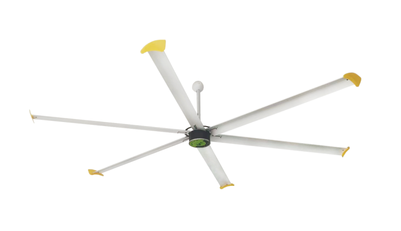
FAQ: HVLS Fan Installation and Efficiency
Q: What is the recommended clearance for HVLS fans?
A: HVLS fans should have 10 to 15 feet of clearance above the floor and 3–5 feet of space between the blade tips and ceiling for optimal airflow and efficiency.
Q: Can HVLS fans be installed in environments with beams or mezzanines?
A: Yes, but they need zone-specific placement to avoid obstructions and ensure uniform air circulation. A site survey should be conducted to map obstacles like beams or mezzanines.
Q: How far apart should HVLS fans be spaced?
A: Fans should typically be spaced 60 to 100 feet apart, depending on blade diameter and target air velocity. High-occupancy zones may require tighter spacing.
Q: What structural requirements are needed for HVLS fan mounting?
A: Suitable supports include I-beams, steel rafters, and reinforced concrete. A structural engineer should assess load capacity before installation begins.
Q: What maintenance protocols are ideal for HVLS fans?
A: Quarterly inspections for blade cleanliness, hardware tightness, and electrical components are recommended. Annual reviews should include load mounts and compliance checks.
Table of Contents
- HVLS Fan Placement Strategy for Maximum Efficiency
- Structural Readiness: Mounting and Load-Bearing Requirements for HVLS Fans
- HVLS Fan Installation: Electrical, Mechanical, and Commissioning Steps
- Post-Installation Validation and Ongoing HVLS Fan Safety Management
- FAQ: HVLS Fan Installation and Efficiency
 ONLINE