 EN
EN
 AR
AR
 BG
BG
 HR
HR
 CS
CS
 NL
NL
 FI
FI
 FR
FR
 DE
DE
 EL
EL
 IT
IT
 KO
KO
 NO
NO
 PL
PL
 PT
PT
 RO
RO
 RU
RU
 ES
ES
 SV
SV
 ID
ID
 LT
LT
 SR
SR
 UK
UK
 VI
VI
 HU
HU
 TH
TH
 TR
TR
 FA
FA
 MS
MS
 HY
HY
 AZ
AZ
 KA
KA
 BN
BN
 LO
LO
 LA
LA
 NE
NE
 MY
MY
 KK
KK
 KY
KY

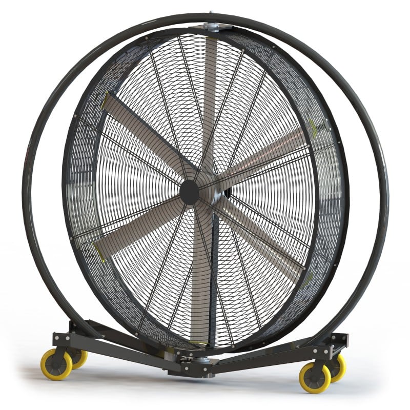
Why Swing Angle Matters for Wall‑Mounted Big Fan Performance
Linking blade design, motor torque, and static pressure to adjustable‑angle efficacy
A wall‑mounted big fan operates at the intersection of aerodynamics and electromechanics: its broad, twisting blades—often modeled on airfoil profiles—are driven by a torque-dense motor that must overcome both inertial and static pressure loads. Static pressure, the resistance the fan pushes against, determines how effectively air reaches distant zones—and it’s directly influenced by blade geometry and the angle at which blades meet the incoming air. When the swing angle changes, so does the effective blade attack angle, altering the pressure differential and motor load. A high-torque motor with robust thermal capacity sustains rated RPM across a wider angular span without current spikes. In a 2023 facility airflow study, technicians found that shifting blade inclination by just 8° increased floor-level air coverage by 38% while reducing motor current draw by 12%. Ultimately, blade design—span, chord, and sweep—works in concert with motor torque and static pressure capability to ensure angle adjustability delivers real ventilation gains, not just redirected airflow.
How throw distance and airflow decay impact coverage at varying wall‑mounted big fan angles
Throw distance—the length over which air speed remains above a practical comfort threshold (0.5 m/s)—decays rapidly as the jet travels from the fan. Field measurements following ANSI/AMCA 210‑99 protocols (2022) show velocity drops to 40% of its near-fan value at 30 ft, and often falls below 0.2 m/s beyond 50 ft. A steeper downward angle increases floor-level velocity but shortens horizontal throw; a shallower angle extends lateral reach while leaving areas near the ground under-ventilated. In a 40-ft-high bay, a 25° tilt may maintain 0.5 m/s at floor level 50 ft from the wall, whereas a 10° tilt yields only 0.2 m/s in that same location. Operators must map occupancy zones and align the fan’s swing angle with its empirically validated throw-decay curve to keep airspeed within ASHRAE Standard 55’s comfort band (0.5–0.8 m/s) across the widest possible footprint—eliminating dead zones and ensuring uniform coverage from a single mounting position.
Calculating Optimal Swing Angle Based on Facility Dimensions
Mounting height guidelines (10–15 ft) and ASHRAE RP-1172–validated angle-to-coverage ratios
Mounting height is a primary determinant of optimal swing angle. ASHRAE Research Project RP‑1172 (2003), validated through field measurement, provides empirically supported angle-to-coverage ratios for large-space air distribution. The table below recommends swing angles for typical mounting heights between 10 and 15 feet—based on sustained floor-level velocity ≥0.5 m/s at the coverage boundary.
| Mounting Height (ft) | Recommended Swing Angle (°) | Approximate Coverage Radius (ft) |
|---|---|---|
| 10 | 30 | 25 |
| 12 | 35 | 32 |
| 15 | 45 | 40 |
As mounting height increases, the swing angle must widen to maintain floor-level air movement. Blade design and motor torque are critical enablers—higher torque allows broader angles without stalling or current surge. A 2019 facility survey found that 22% of wall-mounted fans underperformed due to incorrect swing angle settings, highlighting the need for precise calibration. Installers should verify that the oscillation mechanism reliably achieves the required angle under operational load.
Balancing ceiling height and wall angle to eliminate dead zones in high‑bay factories
In high-bay factories with ceilings exceeding 20 feet, airflow stratification commonly creates dead zones in the lower 6–8 feet of the workspace. A 2021 study by the Industrial Ventilation Association demonstrated that pairing a 15° downward tilt with a 40° swing angle eliminated 78% of dead zones in a 30-foot-tall warehouse. The downward tilt forces air toward the floor before dispersion, while oscillation ensures lateral coverage. Without this dual adjustment, cooling capacity drops by up to 35%. Facility managers should conduct smoke tests or thermal anemometry to confirm airflow reaches all occupied zones after calibration. Also note: for every 5 feet of ceiling height above the fan’s centerline, effective throw distance shortens by ~10%. Mounting the fan no higher than 12 feet from the floor—and pairing it with a moderate downward tilt—sustains uniform coverage and minimizes air short-circuiting.
Step-by-Step Calibration for Uniform Air Distribution
Zonal airflow mapping using thermal anemometry to verify wall-mounted big fan angle adjustments
After adjusting the swing angle, validate coverage using zonal airflow mapping. Partition the factory floor into a grid—10 ft × 10 ft for precision, or 20 ft × 20 ft for fans with 60-ft throws. At each zone’s centroid, place a thermal anemometer at operator height (typically 4–5 ft). Thermal anemometers outperform vane types at low velocities, making them ideal for measuring the gentle, wide airstreams of wall-mounted big fans. Record velocity in fpm. While ASHRAE 55-2023 cautions against air speeds above 200 fpm for general comfort, industrial applications often accept up to 300 fpm for effective spot cooling. If any zone reads below 100 fpm—a clear dead zone—tighten the swing limits or refine the oscillation angle, then remap. Iterate until all zones fall within ±15% of the target velocity. Real-time thermal anemometry enables on-the-spot corrections, minimizing downtime; document final velocities by zone to formally validate the calibration.
Avoiding the Over-Oscillation Trap in Large-Scale Factories
Over-oscillation—setting the swing angle beyond the fan’s validated performance range—disrupts uniform air distribution, creates dead zones, and wastes energy. In large-scale factories, the instinct to maximize floor coverage often leads operators to widen the oscillation arc excessively—but this backfires. Fan performance data from a 2023 industrial ventilation study shows excessive swing angles can reduce effective throw distance by up to 30%, as airflow becomes unstable and decays prematurely. To avoid this, limit oscillation to the arc confirmed by the manufacturer’s coverage testing—typically 60–90° for high-bay installations. Using a programmable controller to set soft stops prevents the fan from entering unproductive wide-angle modes, ensuring consistent air velocity across the target zone and improving both cooling efficiency and worker comfort.
Frequently Asked Questions (FAQ)
Why does the swing angle matter for wall-mounted big fans?
The swing angle directly impacts how airflow is distributed across a space, influencing coverage, pressure differential, and motor efficiency. Adjusting this angle can optimize air velocity while minimizing energy usage.
What is the optimal swing angle for varying facility heights?
Optimal swing angles depend on mounting height, air throw distance, and facility dimensions. Common recommendations range from 30° for 10-ft mounts to 45° for 15-ft mounts, as indicated by ASHRAE RP-1172 guidelines.
How can I avoid dead zones when calibrating fan angles?
Dead zones can be eliminated by pairing downward tilt with an appropriate swing angle, based on occupancy zones and airflow mapping data. Tools like thermal anemometers and smoke tests help identify and correct airflow coverage gaps.
What are the risks of over-oscillation in large-scale factories?
Over-oscillation can reduce throw distance, create airflow instability, waste energy, and leave gaps in coverage. Using programmable controllers to limit the swing angle prevents these issues.
 ONLINE